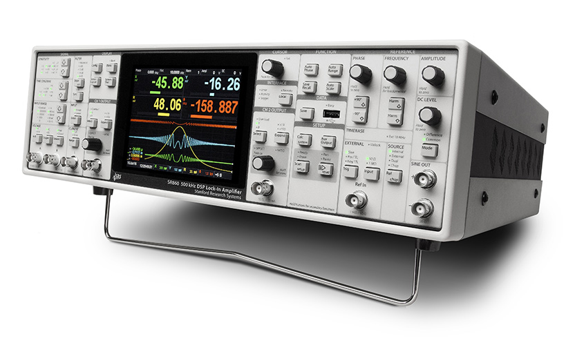
SR860 100 kHz DSP Phase Lock Amplifier
Superb performance. Excellent value for money. They're what you've come to expect from Stanford Research Systems lock-in amplifiers. They're provided by the new SR860 lock-in amplifier, the latest in SRS's innovative lock-in series, which offers unmatched analog performance, advanced new digital signal processing, a completely modern, intuitive user interface, and a wide range of computer connectivity options, making the SR860 the ideal choice for any synchronous detection application.
With over 30 years of phase-locked design experience, SRS has made every effort to optimize every detail of the SR860. From the large toroidal transformer that eliminates switching mode noise, to the iOS connectivity that brings lock-in to your phone, to the advanced DSP filters that eliminate more noise while speeding up experimentation, the SR860 is truly the ultimate lock-in amplifier.
signal input
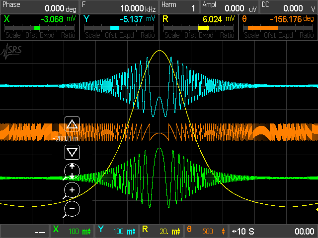
trend chart |
Phase-locked performance starts at the front end, where the SR860 offers state-of-the-art voltage and current input amplifiers. The voltage inputs are switchable single-ended/differential JFET pair amplifiers with noise of 2.5 nV/√Hz at 1 kHz and less than 10 nV/√Hz at 10 Hz. The voltage inputs have a 10 MΩ input impedance and can be AC or DC coupled. The input connector shield can be connected to instrument ground through a user-selectable 10 Ω (ground) or 10 kΩ (float) resistor.
The SR860's built-in current amplifier is a significant improvement over previous designs. The current input range is selectable between 1 μA or 10 nA. The 1 μA range has a 400 kHz bandwidth and 130 fA/√Hz noise, while the 10 nA range offers a 2 kHz bandwidth and 13 fA/√Hz noise.
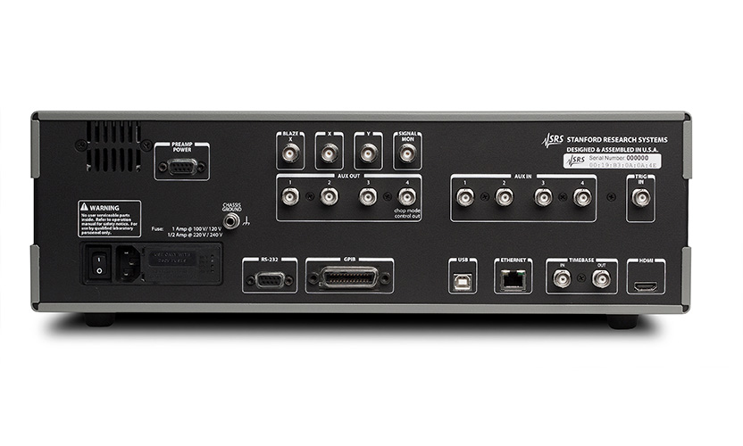
While the built-in voltage and current amplifiers are suitable for most applications, the SR860 is also compatible with the full range of dedicated preamplifiers available from SRS. The SR550 (FET input), SR552 (BJT input), SR554 (transformer input), SR555 (120 kHz current amplifier), and SR556 (low-noise current amplifier) can be powered directly from the rear panel preamplifier power supply port of the SR860. SR860's rear panel preamplifier power supply port.
Sensitivity and Input Range
bar chart record |
As with previous instruments, the sensitivity of the SR860 is set to produce a voltage (or current) at full scale output. However, unlike previous designs, the SR860's input range can be set explicitly from the front panel without reference to the confusing "dynamic reserve" equation. Simply select the desired sensitivity for your experiment, and then select the minimum input range that will not overload the unit. That's it.
The effective dynamic reserve of the SR860 is the ratio of these two settings. For example, with a 10 nV sensitivity setting and a 300 mV input range, the SR860 has an effective dynamic reserve of 3 × 10⁷, or nearly 150 dB.
Output time constant
The SR860 offers conventional RC response output time constants from 1 μs to 30 ks, with roll-offs of 6, 12, 18, and 24 dB/oct. In addition, the SR860 offers advanced digital filters that dramatically reduce measurement time while increasing signal-to-noise ratio. At less than 3 seconds, the advanced filters are Gaussian FIR filters with significantly better rise time and stopband attenuation for the same noise bandwidth as RC filters. These filters also have symmetrical rise and fall curves that preserve the characteristic shape as the frequency is swept. When the time constant exceeds 3 seconds, the advanced filters are linear phase IIR filters that build up almost twice as fast as RC filters to achieve equivalent stopband attenuation.
A synchronization filter can also be selected at reference frequencies below 4 kHz. The synchronization filter cuts out multiples of the reference frequency, which is useful when making low-frequency measurements where multiples of the reference frequency would otherwise be displayed in the phase-locked output. Unlike previous designs, the synchronization filter in the SR860 can be selected without loss of output resolution.
reference channel
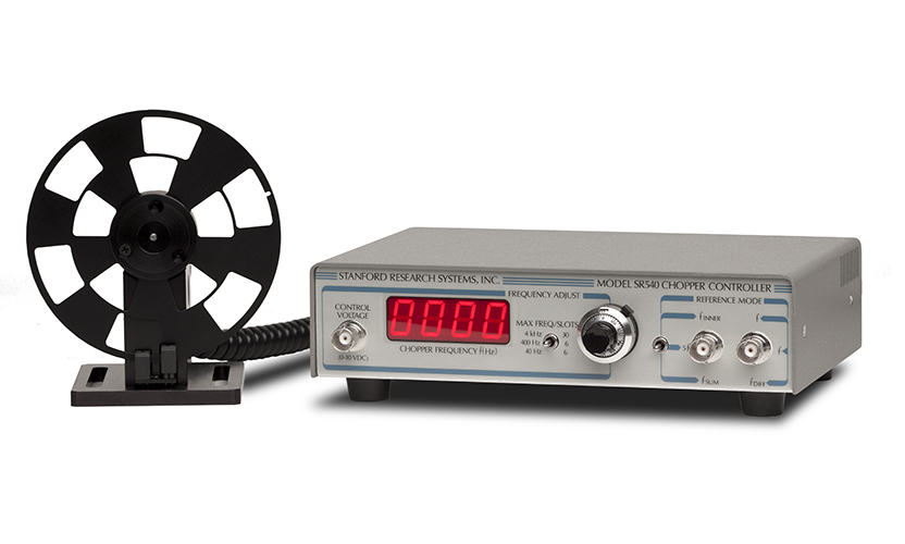
The SR860 has a specified reference frequency range of 1 mHz to 500 kHz, and detection can be performed at the fundamental of the reference frequency or up to the 99th harmonic. Several reference modes are available: Internal mode uses the SR860's precision internal oscillator as the reference. External mode locks to an external sine wave or TTL signal. In dual mode, the phase locker detects the difference frequency between the internally set reference frequency and the externally applied synchronization signal, allowing direct recovery of the dual modulation signal. Finally, in chopper mode, the SR860 provides a digital PID (Proportional Integral Derivative) controller signal to synchronize the SR540 optical chopper with the phase lock's internal oscillator. By allowing the phase lock to directly control the chopper, frequency drift is virtually eliminated.
sinusoidal output
The SR860 provides a precision sine wave output that can be set to 6-bit frequency resolution and an amplitude range of 1 nV to 2 V. The SR860 output is unique in that it can be configured as a single-ended or differential (balanced) signal. The sinusoidal output can apply up to ±5 V DC offset. In addition, the device provides a rear panel logic level synchronization signal that is synchronized to the sinusoidal output.
time base
The rear panel provides 10 MHz inputs and outputs that allow the SR860 to lock to an external frequency reference (such as the FS725 10 MHz rubidium frequency standard). Alternatively, the SR860's 10 MHz output can be used to synchronize multiple phase-locked or other test equipment to the 10 MHz time base input.
FFT Display
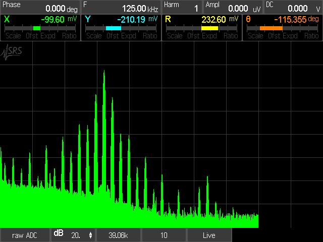
FFT analysis |
Lock-in amplifiers are traditionally time-domain instruments, but sometimes it's easier to understand signals in the frequency domain, and the SR860 is at home in both worlds. the FFT display shows the spectrum of the front-end input signal, the signal after mixing, or the spectrum of the signal after a time-constant filter. Using the FFT display simplifies tracking of sneaky noise sources that would otherwise be lost in the "one number" output of a conventional lock-in amplifier.
Touch Screen Monitor
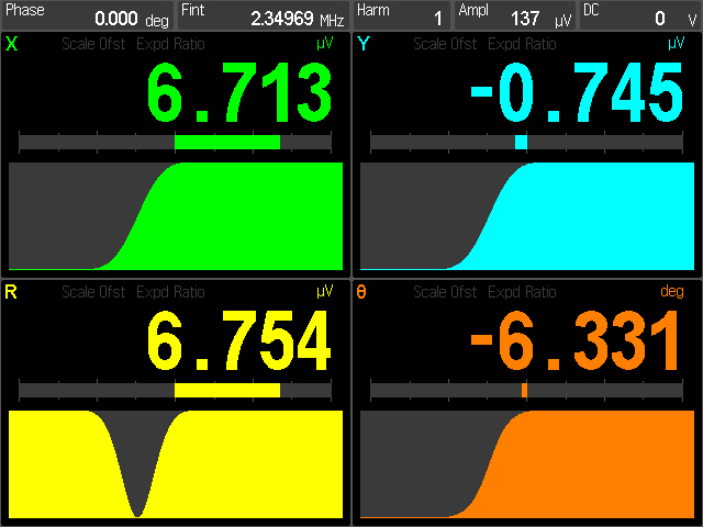
At the center of the SR860's front panel is a full-color 640 × 480 touchscreen that can be set to display up to 4 data channels. (The LCD screen can be masked from the front panel or from a remote interface when the lab needs to be darkened. Each data channel can be configured to display X, Y, R, Θ, Auxiliary Inputs (1-4), Auxiliary Outputs (1-2), X Noise, Y Noise, Sinusoidal Amplitude, Sinusoidal Output DC Level, Reference Phase, or Reference Frequency. The screen can be set to display the data channels as large numbers, easily visible from across the room, or as a "strip chart" display showing the complete history of each channel, with selectable time scales from 0.5 sec/div to 2 days/div. The SR860 always saves all measurements, even when they are not displayed, ensuring that no data is lost. Even when no measurements are displayed, the SR860 always saves all measurements, ensuring that no data is lost. The touchscreen also continuously displays key-locked setup parameters such as phase, reference frequency and sine wave amplitude. The rear panel HDMI port allows the LCD screen to be viewed on any HDMI monitor or TV.
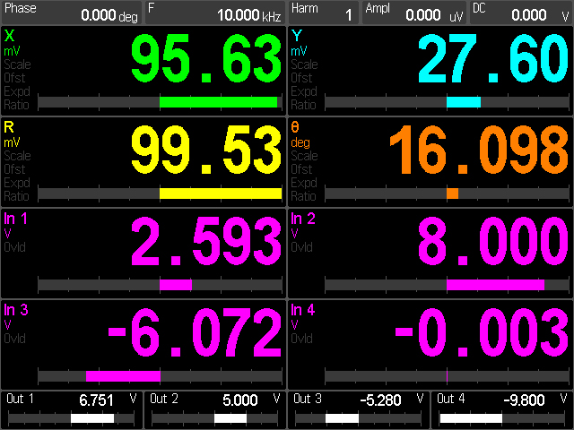
digital reading |
It should be emphasized that while the touch screen monitor is useful for displaying data, it is not necessary to use the touch screen to control common instrument functions on the SR860. All commonly used controls: time constant, reference frequency, sine amplitude and offset, input configuration, etc., can be controlled via dedicated front panel knobs or buttons. Infrequently accessed configuration settings, such as TCP/IP settings and other communication settings, can be accessed through menus displayed on the touchscreen.
computer connection
The SR860 comes standard with almost every conceivable remote interface. Of course, GPIB (IEEE488.2) and RS-232 are also available, as well as USB (test and measurement class) and Ethernet (VXI-11 and telnet.) The SR860 has its own web server, which allows the instrument to be remotely monitored and controlled with just a browser.
The front panel USB port allows data and screen shots to be transferred to a USB flash drive. Data can be saved as a comma delimited file or as a MATLAB compatible file. Merging screenshots and data into a report or spreadsheet has never been easier.