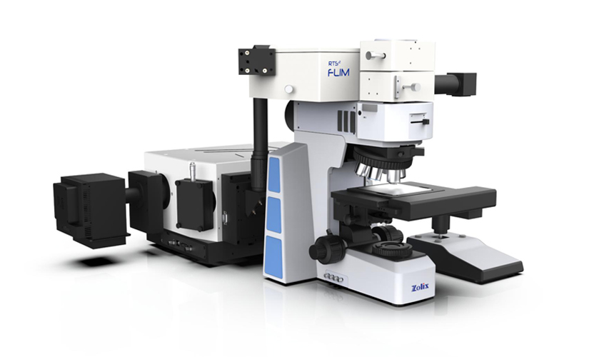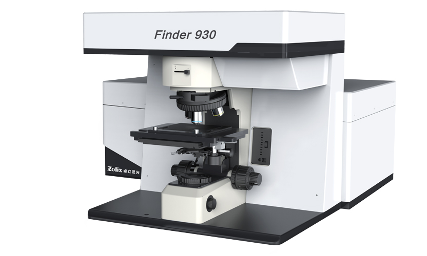
Product Overview
From 2003 into the field of Raman spectroscopy, Joyo's technical strength continues to precipitate, Raman products are also pushing the new, the company's products in the materials, geology, biology, chemistry, medicine, food, criminal investigation and other fields have been very widely used. After long-term discussions with different customers in different industries, we launched a new generation of Finder 930 Raman measurement system, aimed at creating a high performance, high stability, high cost-effective high-end domestic laser confocal Raman spectrometer belonging to the country's own. Drawing on the successful experience of the previous generations of products, we have upgraded the hardware and software of Finder 930 in an all-round way:
- The imaging quality is more, the wavelength repeatability and accuracy is higher, so that your experimental data is more reliable.
- The automatic correction of the optical path not only makes the equipment more intelligent and easier to operate, but also improves the stability of the equipment, which can be used immediately after powering on, without the need for specialized maintenance.
- mapping, Raman mapping, fluorescence lifetime imaging, hyperspectral data processing, easy to use, so that your data analysis is more convenient and quick.
- The Finder 930 is a high-performance, highly reliable, intelligent and versatile analyzer for your research.
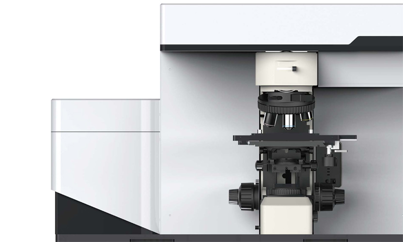
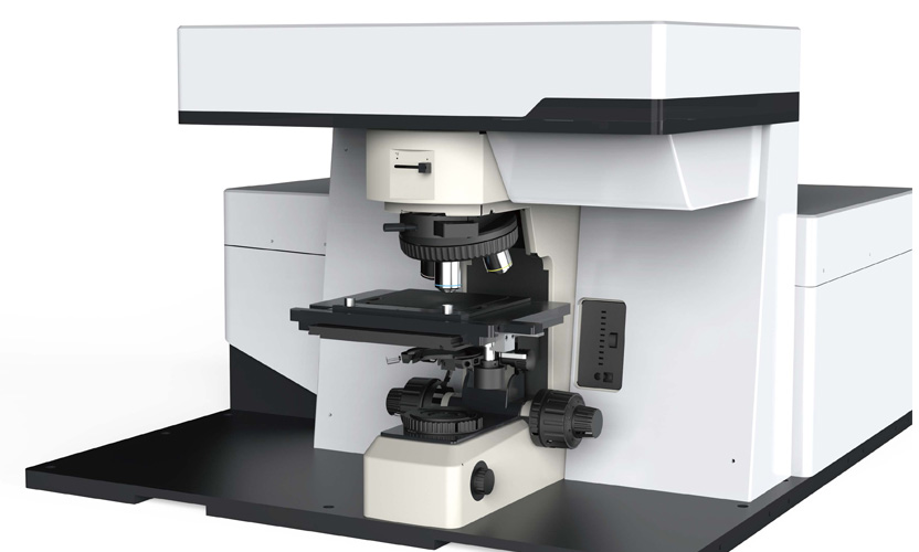
System FeaturesVery high confocal performance
When a point light source (usually a laser) is focused on a sample through the objective lens, the image made at this point is detected by the detector through the detector pinhole, at which time the illumination pinhole and the detector pinhole are conjugate with respect to the focal plane of the objective lens, i.e., confocal. In confocal microscopy, only the scattered light signal of the illuminated sample is accepted, which ensures lateral spatial resolution, while the signal of the sample located in the illumination area of the light source but not in the focal plane is strongly attenuated by the detector pinhole (spatial filter) due to out-of-focusing, which ensures longitudinal spatial resolution. Therefore, when we move the sample up and down in the direction of laser incidence, we can focus the laser on different layers of the sample to enable profiling of the sample. Another advantage of confocal is the excellent background suppression for transparent and semi-transparent samples, or samples with a strong background of fluorescence and blackbody radiation.
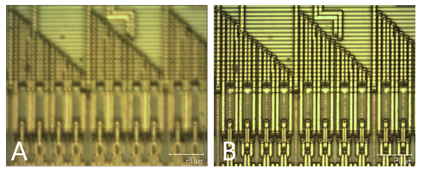
As shown above, in wide-field imaging (A), out-of-focus light significantly reduces the resolution and contrast of the image; however, in a confocal imaging system (B), the use of pinholes to remove out-of-focus light creates an image with higher contrast and resolution.
Excellent system stability
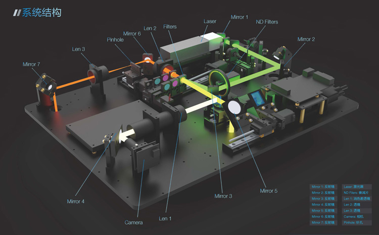
In an optical system with many optical components, the temperature drift of the optical components adjustment frame, the repeatability of the optical path switching, etc., directly affects the stability of the system, which is reflected in the micro confocal Raman spectroscopy system * intuitive phenomenon is the laser spot drift. The laser spot drift will bring many problems, * direct impact is the confocal performance and system sensitivity degradation, and secondly, spot drift will be polarization and other very high requirements on the collimation of the optical path of the experiments brought about by the impact of the system to ensure the stability of the design of all the optical system of the first issue.
- Effect of temperature and humidity on stability
In an optical system, the longer the optical path and the more mirrors there are, then the greater the amount of drift in the optical adjustment frame due to the effects of temperature and humidity, and the more severe the laser spot drift will be. As can be seen from the principle of confocal, confocal is to image the laser spot onto the pinhole, laser spot drift means that the spot image on the pinhole drifts, so the throughput drops significantly. In order to avoid signal strength being affected, the pinhole can therefore only be made larger, which in turn affects the confocal performance. To solve this problem, the Finder930 adopts a laser-integrated design, which reduces the optical path length to a large extent, and an optics adjustment bracket made of aircraft aluminum, which has minimal deformation due to temperature and humidity.
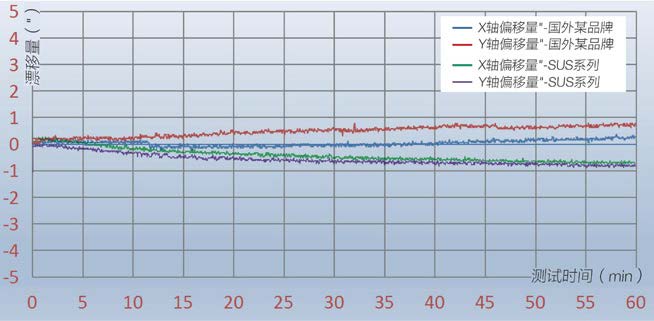
Experimental test curves for time stability:
- Effect of optical path switching on stability
When the confocal Raman system is configured with multiple lasers to meet different experimental needs, it is necessary to switch the lasers and filters, and because the switching process requires high positioning accuracy and repeatability, motorized switching is usually used. When changing the wavelength of the laser, the software will automatically control the switching of the laser and automatically switch to the responsive filter. The above design ensures that the system can work stably for a long period of time (several months) without the need to adjust the optical path frequently.
Temperature stability experimental test curve:
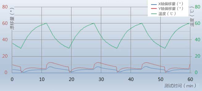
Note: The curve is laboratory test data, ambient temperature 22±2℃.
Excellent spectral imaging capabilities
Raman spectroscopy is a tool used to characterize the chemical composition of substances and to study molecular properties such as stress, polarity, and crystal quality. Raman mapping or Raman imaging is a means of visualizing the object of study. Users can visualize the spatial distribution of chemical compositions directly from the Mapping image.
Since Mapping is a type of microscopic image, Mapping must have the characteristics that a microscopic image should have, i.e., spatial resolution and imaging speed.
1. Spatial resolution
The spatial resolution is divided into two indexes: horizontal (XY plane) and vertical (Z). The horizontal resolution is mainly affected by the NA of the objective lens, the wavelength of the laser, the size of the confocal aperture, and the quality of the laser spot, while the vertical resolution, which is also called the confocal performance, is greatly related to the optimized design of the system in addition to the above factors. The optimized Finder930 can achieve a horizontal spatial resolution of 0.5m and a vertical spatial resolution of 1.79m under the test conditions of a 100X, 0.9NA objective lens and a 532nm laser, and all of our mapping can be done under confocal conditions, thus ensuring the spatial resolution of the mapping results.
2. Imaging speed
Mapping speed is another important parameter, which mainly depends on the sensitivity of the system, the precision of the motorized stage and the processing capability of the software. The sensitivity should be high enough so that the acquisition time of a single spectrum can be shorter and the Mapping speed can be improved essentially, while the high precision of the motorized stage is mainly to prevent image distortion, the Mapping logic of the software is to improve the Mapping speed and achieve the synchronization function of picking up the spectrum while walking, and the real-time processing capability of the software, such as noise suppression, background deduction, etc. can extract the Raman spectrum from the weak and complex signal for real-time display. The real-time processing capability of the software, such as noise suppression, background deduction and other functions, can extract Raman spectra from weak and complex signals for real-time display.
2.1 System sensitivity: silver-plated mirrors, upgradable broad-spectrum dielectric film; spectrometer can be upgraded with silver plating; F/4.2 aperture; CCD adopts deep-cooling, back-illuminated deep depletion chip, peak quantum efficiency >90%; 1.48MHz readout speed, which can realize more than 100 spectral acquisition speeds per second.
2.2Mapping When acquiring images, the motorized displacement stage first moves from the origin to the zero point of the acquisition target area, and then scans point by point and line by line in accordance with the program design, and after the end of scanning, the motorized displacement stage returns to the center of the scanning area. At this point, the acquired spectra can be processed to obtain the ideal Raman Mapping image.
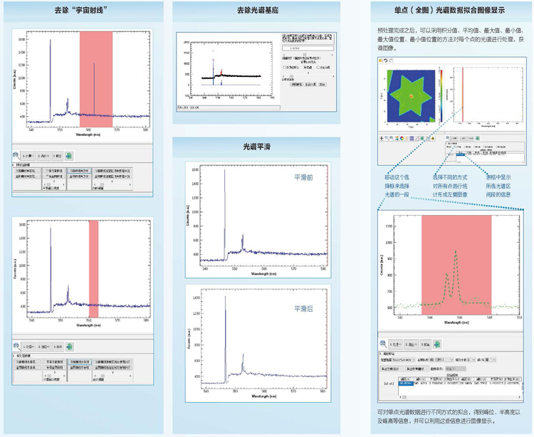
Software data analysis (Visual Spectra)
With powerful data analysis software, Mapping data can be pre-processed by de-baselining, smoothing, etc., and then, according to the needs of imaging through the integration of signal intensity, average, *maximum value and other modes; in addition, single-peak and multiple-peak data can be fitted. In addition, single-peak and multi-peak data can be fitted. For the output image, color matching and other beautification processes can be performed.
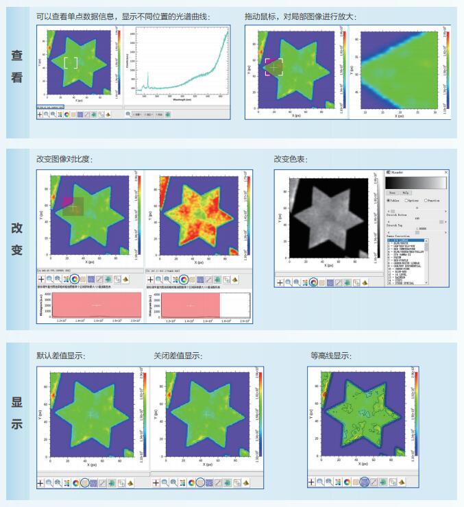
Spectral Mapping Data Processing Pre-processing of single point (whole map) data, including removal of "cosmic rays", spectral base, smoothing of spectral curves, etc. is possible.

objective (optics)
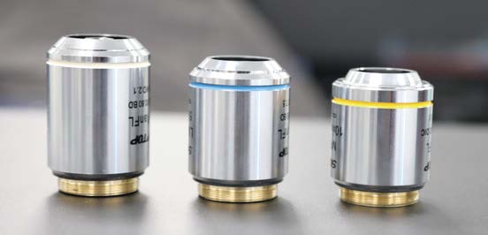
Model & Description
SLMPLN20X: Long working distance objective, NA value 0.25, working distance 25mm, thread size RMS, 45mm flush distance;
SLMPLN50X: Long working distance objective, NA value 0.35, working distance 18 mm, thread size RMS, 45 mm flush distance;
SLMPLN100X: Long working distance objective, NA value 0.6, working distance 7.6 mm, thread size RMS, 45 mm flush distance;
LMU-15X-NUV: UV objective lens, wavelength band 325-500nm, NA0.3, working distance 8.6mm, thread size RMS, flush distance 39.1mm;
LMU-40X-NUV: UV objective lens, wavelength band 325-500nm, NA 0.47, working distance 0.8mm, thread size RMS, flush distance 34.5mm;
LMPLN10XIR: Infrared objective lens, wavelength band 700-1300nm, NA value 0.3, working distance 18mm, thread specification RMS, flush distance 45mm;
LCPLN50XIR: Infrared objective lens, wavelength band 700-1300nm, NA value 0.65, working distance 4.5mm, thread specification RMS, flush distance 45mm;
LCPLN100XIR: Infrared objective lens, wavelength band 700-1300nm, NA value 0.85, working distance 1.2mm, thread specification RMS, flush distance 45mm;
Electrochemical accessories
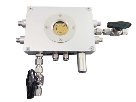
It can be used with various Raman and infrared spectrometers (reflectance) for spectroscopic testing under in-situ conditions, and is widely used in chemistry, materials and related fields, especially suitable for basic electrochemical research. This device is of research type and can be expanded according to the needs.
Key Features:
- Raman, IR compatible;
- Gas permeable;
- Different windows available
- *Small focal length of 1mm;
litter table
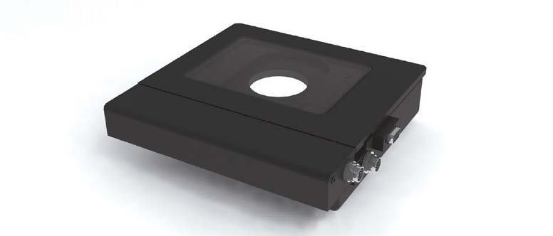
- 75 x 50 Stroke, Control Handle
- 3m positioning accuracy, *Small step 50nm;
- 2D Raman/PL Mapping
- *Large load capacity of 1kg;
high pressure chamber
The Hydrothermal Diamond Chamber is a new type of diamond chamber device that enables phase transition experiments to be observed under a microscope in the high temperature and high pressure or low temperature and high pressure aqueous regime. It utilizes two diamond anvils to generate high pressures of up to 3 to 5 GPa by compressing and sealing the rhenium chamber gasket in the middle of the diamond anvils. A heating assembly consisting of a tungsten carbide support, molybdenum heater wire, ceramic binder, thermocouple, and shaking table provides temperatures up to 1000°C. The heating assembly is used in conjunction with a microscope or laser Raman. In combination with a microscope or laser Raman, the phase transition process can be observed and changes in the composition of the reactants can be measured. It can be used for methane hydrate experiments, high-pressure phase experiments on H2O ice, granite melting experiments, combined rock and mineral melting experiments, and pyrolysis experiments on combustible organoclasts, petroleum, montmorillonite, and rocks, as well as studies of inclusions in minerals.
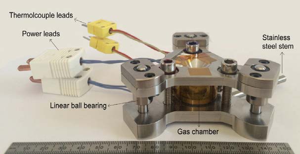
- Temperature range: room temperature to 1000°C;
- Temperature accuracy: +/- 0.1℃;
- Heating rate: 0.1 to 150°C/min;
- Pressure range: atmospheric to 3GPa (standard);
-
Low temperature range: to -100°C (special requirements);
temperature console
- Temperature range: -190℃~600℃;
- Temperature resolution: 0.01°C;
- Temperature stability: ±0.05°C (>25°C) ±0.1°C (<25°C);
- *Maximum heating speed: +150°C /min;
- *Maximum refrigeration speed: -50℃ /min
- *Small objective lens distance: 5 mm;
In situ spectral stretching device
It is a testing device that can be applied to infrared, ultraviolet and fluorescence research under the conditions of sample stretching. The in-situ infrared, ultraviolet and fluorescence tensile device is designed according to the tensile effect required by the material, and with the structural space requirements of the corresponding spectrometer, it is able to realize the tensile test requirements of the samples; and its structural design takes into full consideration of the infrared, ultraviolet and fluorescence test requirements under laboratory conditions, and sets up the corresponding window to ensure the transmission of the light and the detection of the fluorescence outgoing from the 90 ° direction.
- Displacement stretch adjustment range: 0.1-20mm;
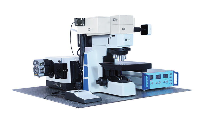
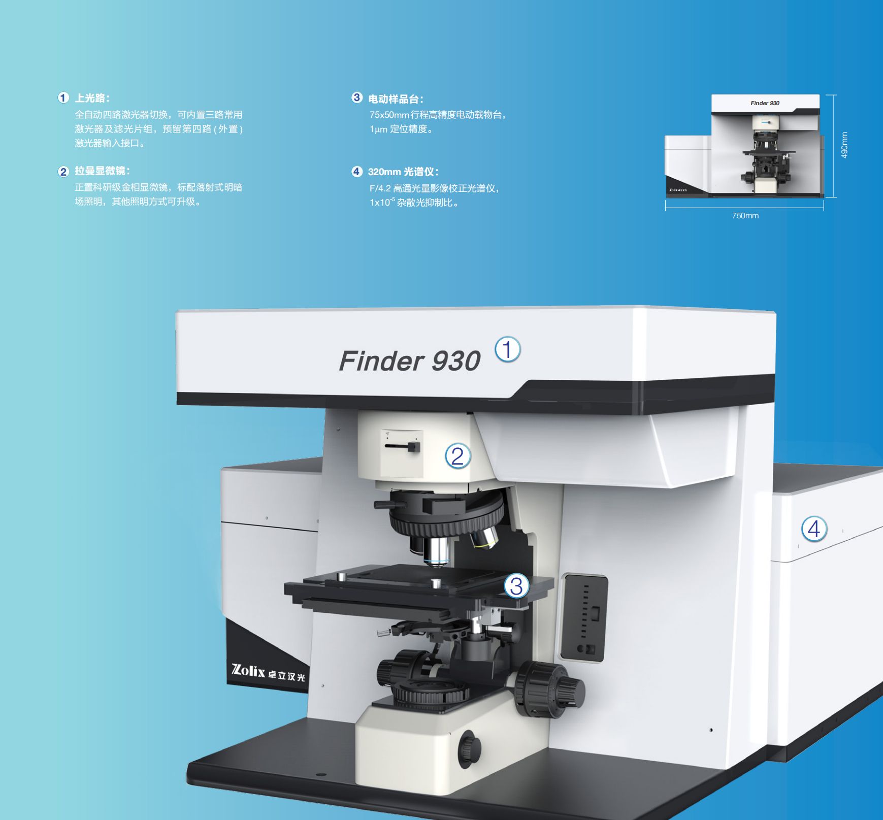
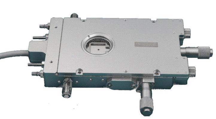
Finder 930 Series Fully Automated Raman Spectroscopy SystemSystem specifications
| Laser wavelength (nm) | Standard 532nm, optional 638nm, 785nm |
| Laser power (mW) | >60 (532nm), >25 (638nm), >50 (785nm) |
| Raman frequency shift range (cm-1) | 80-9000@532nm, 80-6000@638nm, 80-3200@785nm |
| microscopy | orthoptic microscope |
| sample stage | Standard: manual, stroke 102*105mm |
| Option: Motorized displacement table, stroke 75*50mm | |
| objective (optics) | 10x, 50x, 100x, Semi-Apochromatic |
| downlighting | LED light source |
| spectrograph | 320 mm focal length, Czerny-Turner style |
| Spectral CCD | ≥2000×256 pixels, back-illuminated deep depletion chip, QE>90%, visible NIR only |
| Grating Configuration | 1800g/500nm blazed |
| 600g/500nm blazed | |
| 150g/500nm blazed | |
| spectral resolution | < 1.5cm-1 |
| signal-to-noise ratio | > 30:1 |
| spatial resolution |
Vertical resolution: <2μm@50μm pinhole, 532nm laser;
≤1μm@10μm pinhole, 532nm laser
|
| Horizontal resolution: <500nm@532nm Laser |